I wanted to get a limited slip/torque biasing differential in my car, since I was going to rebuild the transmission. I was considering a differential made to fit the 1st and 2nd generation Civics by MFactory, but I was pointed to the Quaife unit after inquiring about the dimensions of the 1st and 2nd generation Civic differential's dimensions in order to compare them to the one I had. Quaife has a technical drawing of the differential which shows its major dimensions. They didn't seem to match my differential, but this was the most feasible option, compared to cutting a boss into a 1st-2nd generation civic differential, for the speedometer, or finding a period clutch-type LSD which might not be rebuildable due to parts availability and age. The Quaife was bought around the beginning of June 2021.
Based on my research, there is no shared differential between Honda Civics or Honda Citys which fulfill the dimensions given by Quaife.
https://docs.google.com/spreadsheets/d/1r1MYDXjU5iHLuD2SsdYbDd18wRaEIWrgBZkvuNGL3d8/edit?usp=sharing
However, upon further investigation later on, I found the most likely vehicle this differential was designed to fit is the second generation Japanese-market Honda City GA1-GA2. This differential is not shared with any other models.
This post seems to corroborate my chart, at least for the City Turbo II with the differential driven speedometer. However, it somewhat proves this was done before.
https://www.cityturbo.com/forums/viewtopic.php?f=3&t=2422
This post further alludes to compatibility with modification, although it is not outlined
https://www.cityturbo.com/forums/viewtopic.php?f=3&t=2422&p=18394&hilit=quaife+machining#p18394
Initially, I wanted to drill holes in the actual differential, so I did it since I was in a rush due to a self-imposed time constraint; I wanted to get it done before school started (this was around June-July). I wanted to drill into the differential, since there would have been little material to spare on the ring gear if I re-drilled it to 120mm PCD (the holes would have been within ~1-2mm of the hole, and it would have gone a decent amount into the chamfer on the hole, reducing the clamped area), while there was more material to spare on the differential. In retrospect, that was stupid idea since my drill press did not have enough precision, and I used too small of a drill bit. I used the right size to tap the holes, but the differential case is hardened.
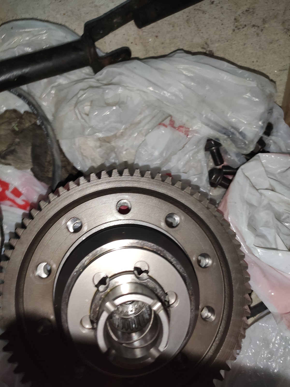
At the time, I lacked knowledge of the capabilities of High Speed Steel and what surface hardness demonstrates, and I did not think the drill press would be so imprecise. I know better now, at least. It also seemed like a major time and extreme monetary investment, to determine the type of metal, to anneal it and then harden again without any warping, so I did not pursue this path further. The position of the holes was way off as well, due to using the drill press.
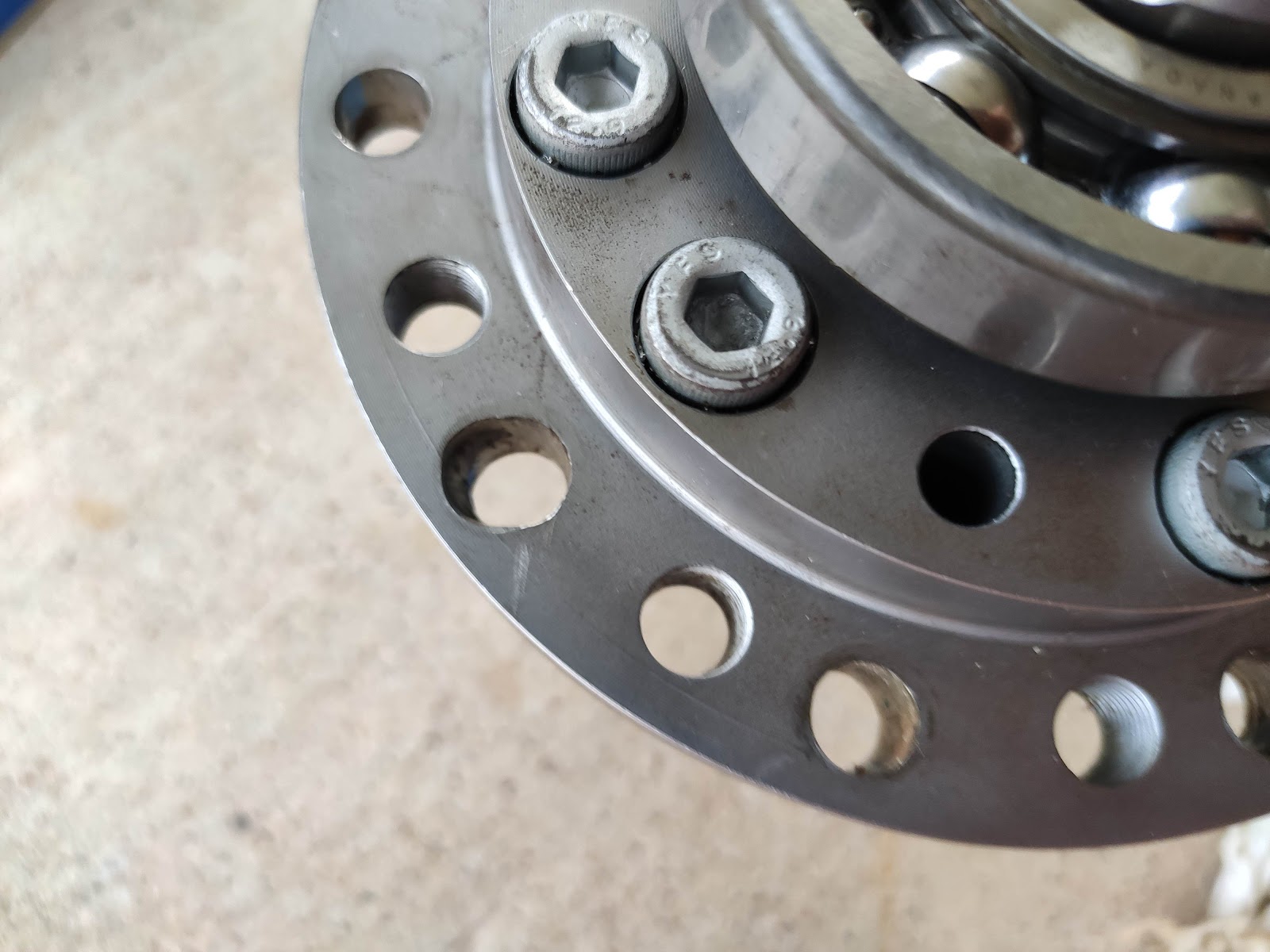
This made it so my bolts were too small; the cross sectional area was only about 60% of the original bolts. I had tried M8x1.25 bolts with nut, and found they would work. Back calculating with the torque specifications of the original bolts, even using grade 12.9 bolts would not have been enough to compensate. Even if I repositioned the holes properly to use M10 bolts, like what was originally used, there could have been clearance issues with the bolt heads since they would have been larger than M8, and with my arrangement, they could have fit first gear on the transmission countershaft which would be bad. Since this must be checked with the transmission partially assembled (the countershaft is located by a ball bearing. It must be tightened properly against it to properly set the clearance and there was no reasonable way for me to observe the clearance if the gearset has any play under load (both engine braking and acceleration).
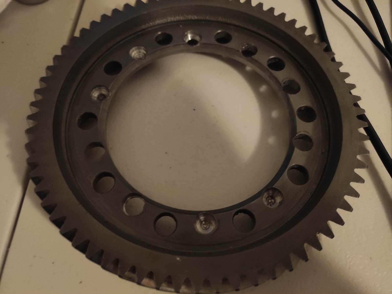
However, I had access to my University's machine shop, which I learned I could use during an introductory class, which I used to drill the bolt holes on the differential ring gear. I avoided this initially due to the aforementioned reasons, but after trying it the other way unsuccessfully, and with more substantial complications than expected, this became a more appealing option. Other than those 2 observations, the proper size bolt (original sized bolts) could be used, with none of the associated clearance issues from using a bolt-nut arrangement.
The drilling was easily accomplished, since the mill had a digital readout. Centering the new holes between existing ones was more difficult, but for this application it probably does not matter unless it is very off since the gear is clamped onto the flange, which could reduce/normalize local stress compared to a pin connection but I am not certain. This was done in December 2022, with some holes fully drilled, and some spot drilling at school, with the holes being finished at home with the drill press (the spot drilling allowed for enough precision).
I also wanted to use the original speedometer gear. Various spacers were tried, but I decided none of the manufacturing methods I had at my disposal could yield a satisfactory result (tight press fit with both the gear and the differential). I decided to use a online 3D printing service, and replicate the speedometer gear. It was fairly simple; I roughly replicated the trapezoidal profile of the cross section (made it smaller so I would not have any clearance issues even with inaccuracies due to 3d printing) in SolidWorks, measured the pitch of the helix, and did a simple sweep along a spiral profile. I had wanted to finish it as soon as possible, so when I saw it press fit on easily, I just shelved it since I wanted to get it done over winter break.
I had also made a spacer ring for the ring gear, but I had too much runout using one of the University's lathes (I wanted to keep the runout of the ring gear under 0.004 in which seems to be specified in later Civics' owner's manuals. I roughly checked this by holding the end of a flat punch just close enough so the gear teeth would skim the punch, and I rotated it around and checked the clearance between the punch and a piece of paper, which is around 0.003 in thick), so I got a machine shop to do that.
After reassembling the transmission, I realized the axle tubs on the differential are not in the same position as the original differential, so I used slightly thicker oil seals to compensate. Importantly, the main sealing lip has a greater offset from the lower surface of the oil seal, which allows for it to sit tightly in the hole for the axle seal, while maintaining the required offset for it to stay in contact with the boss on the axle.

After addressing this, I drove the car for a while. The first major issue was that the plastic speedometer gear I put on the differential came loose. In retrospect, it was wishful thinking it could have survived. Part of the cause seemed to have been due to unequal tire pressures between the left and right front tires. I had pumped them up after reassembling the car, but the gauge I was using was inaccurate, resulting in the car pulling noticeably. I had written it off as torque steer from the differential, since the car has unequal length axles and even in a neutral position, they are slightly angled forward/back, or changes to the suspension, since I had changed the suspension arms.
Since geared differentials work through inefficient gear systems where, in this case, planetary worm gears are forced against the case of the differential, which allows for torque biasing. The unequal tire pressures might have caused the differential to be in a 'locked' state. Friction could have generated heat and loosened the speedometer gear. However, perhaps it would have experienced thermal creep over time anyways. If I had given myself more time and planned things out more meticulously over a longer period had I known it would have taken nearly a year anyways; this first drive happened in June 2022. I could have used a few of those notches on the boss next to the axle tube pictured below.
